
Product Overview
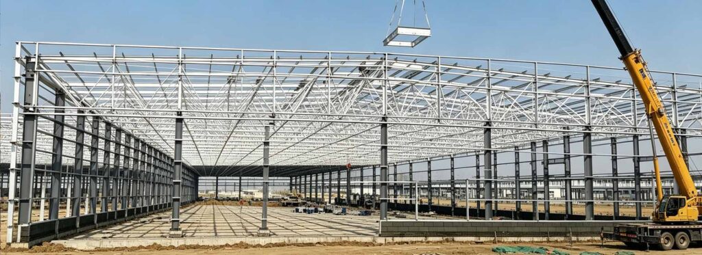
Space Truss is a three-dimensional triangulated structural system used to distribute roof loads across multiple directions. It is supplied as a project-specific solution rather than a fixed catalogue item. Geometry, member sizes, connections, protection systems and delivery segmentation are confirmed from approved documents.
The engineering and fabrication scope can coordinate perimeter supports, roof panels, skylights, services and erection towers. Early review of drawings, loads, site conditions and transport limits helps define a practical supply package and reduces interface risk.
Product Core Parameters
| Product type | Space Truss |
|---|---|
| Primary configuration | three-dimensional triangulated structural system used to distribute roof loads across multiple directions |
| Engineering basis | Approved project drawings, loads, site conditions and applicable codes |
| Dimensions / span | Project-specific |
| Material grade | Defined by approved design and procurement specification |
| Connections | Welded, bolted or combined as detailed |
| Inspection | Approved inspection and test plan; specified NDT where required |
| Surface protection | Selected for exposure, service life and maintenance plan |
| Delivery | Component size, marking and sequence coordinated with transport and erection |
Key Features
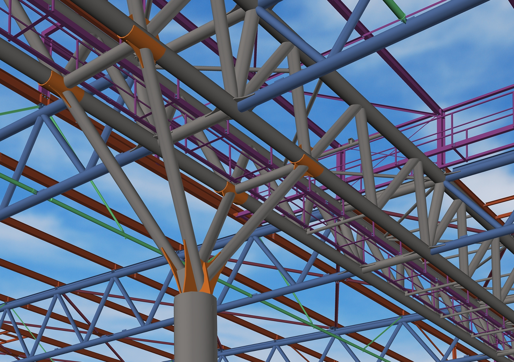
- Project-specific engineering: The space truss is developed around three-dimensional geometry, node forces, support movement and global stability; final member sizes and details follow approved calculations and drawings.
- Coordinated interfaces: Design and detailing account for perimeter supports, roof panels, skylights, services and erection towers, reducing conflicts during fabrication and site assembly.
- Controlled prefabrication: CNC processing, documented fit-up and controlled welding improve dimensional consistency and traceability before shipment.
- Connection detailing: Bolted, welded and bearing interfaces are coordinated with the actual load path, access, tolerances and erection method.
- Inspection planning: Material verification, dimensional checks, weld inspection and specified NDT are tied to the approved quality plan.
- Delivery-ready documentation: Member marks, packing lists, inspection records and erection information are prepared to match the agreed supply scope.
Main Components
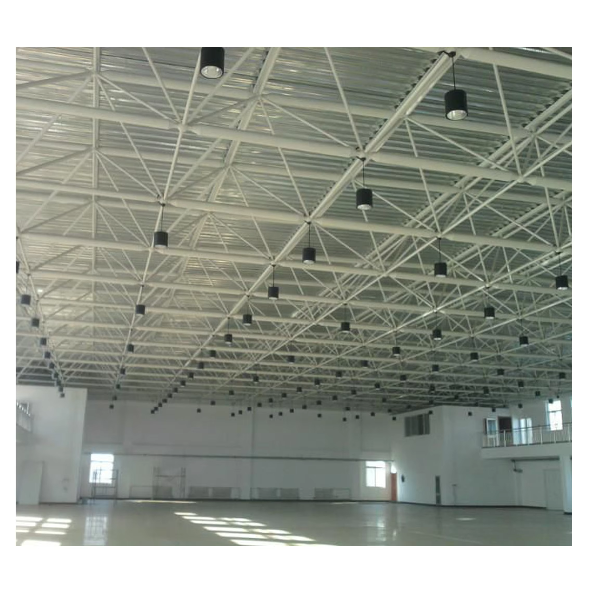
The exact bill of materials is project-specific. A typical space truss package may include:
- 01 — Upper and lower chord grids: Detailed and fabricated according to its structural function, connection requirements and approved drawings.
- 02 — Diagonal web members: Detailed and fabricated according to its structural function, connection requirements and approved drawings.
- 03 — Node and connection assemblies: Detailed and fabricated according to its structural function, connection requirements and approved drawings.
- 04 — Perimeter support and bearing zones: Detailed and fabricated according to its structural function, connection requirements and approved drawings.
- 05 — Secondary roof-support steelwork: Detailed and fabricated according to its structural function, connection requirements and approved drawings.
- 06 — Bracing, drainage and erection interfaces: Detailed and fabricated according to its structural function, connection requirements and approved drawings.
Typical Applications
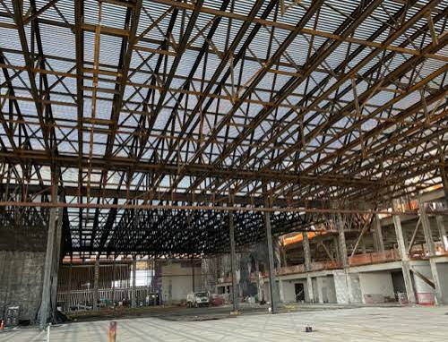
01 — Large exhibition and sports halls
Suitable where the project requires three-dimensional geometry, node forces, support movement and global stability. Final suitability depends on loads, geometry, site conditions, interfaces and applicable regulations.
02 — Transport terminals
Suitable where the project requires three-dimensional geometry, node forces, support movement and global stability. Final suitability depends on loads, geometry, site conditions, interfaces and applicable regulations.
03 — Industrial and public long-span roofs
Suitable where the project requires three-dimensional geometry, node forces, support movement and global stability. Final suitability depends on loads, geometry, site conditions, interfaces and applicable regulations.
Manufacturing & Delivery
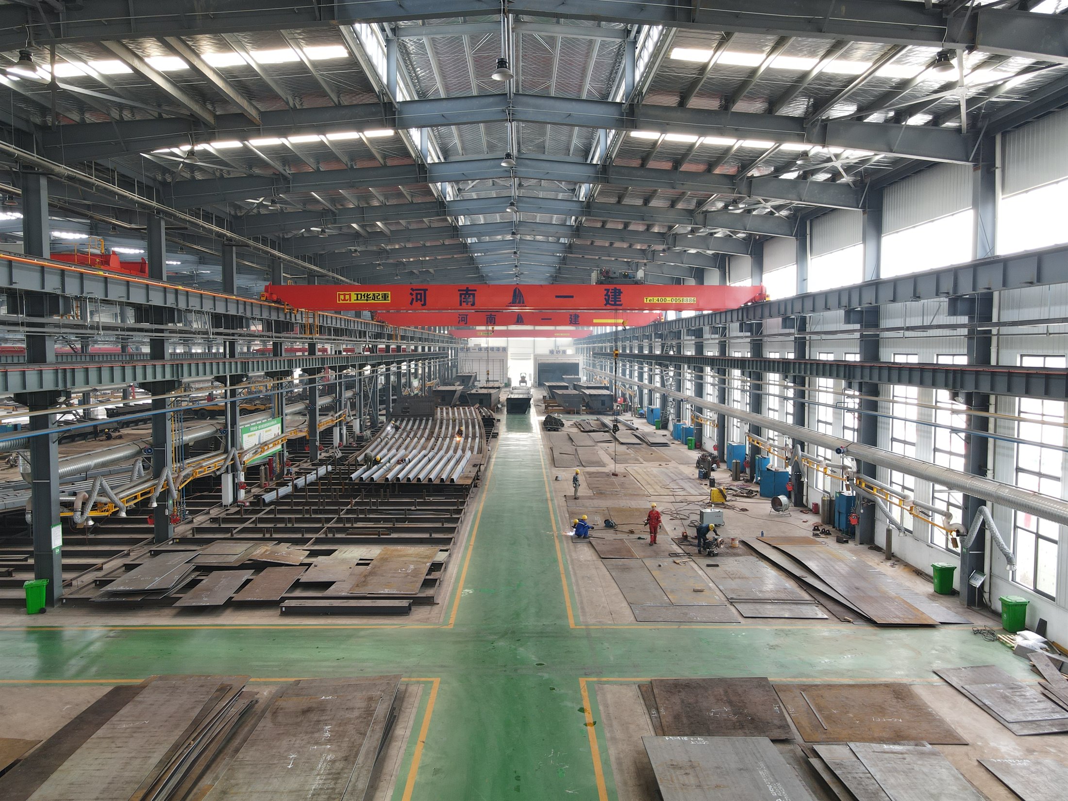
- Review geometry, support layout, architectural envelope and design loads
- Develop the structural model, member forces, nodes and support movements
- Coordinate fabrication modules, transport limits and erection method
- Verify materials, node components and traceability
- Perform CNC cutting, end preparation, drilling and controlled welding
- Inspect member geometry, nodes, welds and specified NDT
- Conduct trial assembly or digital/interface verification where required
- Apply protection, mark modules and prepare erection drawings
- Deliver in the planned lifting and assembly sequence
Project Customization
Customization can cover overall geometry, member sections, material grades, connections, openings, interfaces, inspection scope, coating system, fire protection, packing and erection sequence. For a technical review, provide the project location, design basis, drawings, loads, quantities, required standards, inspection requirements, finish and delivery destination.
Quotation input: architectural or structural drawings, dimensional schedule, load criteria, material specification, connection responsibilities, coating requirements, quality documentation and target delivery program.